benlong


What Is an MCCB Automatic Assembly and Testing Line? A Complete Technical Guide
An MCCB automatic assembly and testing line is a fully integrated production system that automates the complete manufacturing process of molded case circuit breakers — from mechanical assembly and break-in, through thermal and magnetic trip calibration, to hi-pot testing, pad printing, and final packaging — within a single continuous production flow. By combining multi-station assembly, precision constant current sources, and inline quality inspection under unified PLC and MES control, it eliminates the manual errors, traceability gaps, and throughput bottlenecks that define conventional MCCB production, achieving cycle times of 60 to 120 seconds per complete unit across product ranges from 63A to 800A.
The MCCB is the protection device of last resort in industrial and commercial electrical distribution. Every unit leaving a production line must demonstrate that it will trip reliably under overload conditions and survive decades of mechanical operation in the field. Verifying this at production scale — across multiple pole configurations and ratings, with full unit-level traceability — requires automation that is fundamentally different from anything used for smaller MCB production. This guide covers how a Benlong MCCB automatic assembly and testing line achieves that, station by station.
Why MCCB Production Cannot Scale Without Full-Line Automation
The MCCB presents assembly and testing challenges that are structurally more complex than the MCB. The reasons are physical: an MCCB carries 63A to 800A or more, uses multiple distinct trip mechanisms (thermal-magnetic, electronic trip unit, or both), and must meet both GB 14048.2 and IEC 60947-2 — standards with demanding and multi-step verification requirements.
Assembly complexity. An MCCB contains more components than an MCB, with tighter positional tolerances. Manual assembly at volume produces dimensional scatter in critical parameters — opening distance, overtravel, final pressure — that accumulates across stations and produces products that are borderline on mechanical characteristics before they reach the test station.
Testing duration. Thermal trip calibration for an MCCB — particularly at higher ratings — requires sustained overload current application for minutes at a time. A manual test station can process only a handful of units per hour. An automated line runs multiple positions simultaneously, with automatic current application, timing, and pass/fail decision.
Multi-specification production. MCCB manufacturers typically run 2P, 3P, and 4P configurations across multiple frame sizes (63, 125, 250, 400, 630, 800 series) from the same line. An automated line with one-key recipe switching handles this without mechanical tooling changes between same-frame products — a capability that manual production cannot replicate.
How a Benlong MCCB Automatic Assembly and Testing Line Works: Station by Station
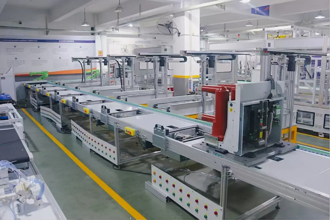
A complete MCCB automatic assembly and testing line groups its functions into sequential process stations. Units flow between stations automatically on a conveyor system, and every station is interlocked — a failure or out-of-tolerance result at any point diverts the unit without stopping the line. The following describes a full-featured Benlong line configuration covering both assembly and testing phases.
Station 1 — Automatic Loading and Labeling
MCCB cases are loaded onto the conveyor — automatically from upstream injection or manually from a staging rack depending on line configuration. A 2D barcode label is applied at this station, creating the unit-level identity record that travels with the product through every subsequent station. All test results, calibration data, and process parameters are linked to this barcode in the production database from this point forward.
Station 2 — Core Component Assembly
Internal components — contact system, arc chamber, trip mechanism, and terminal hardware — are assembled into the molded case. This station can be configured for full automatic assembly or semi-automatic assembly depending on product complexity and production volume. Vision systems verify component presence and orientation before the assembly fixture releases to the next station.
Station 3 — Mechanical Break-In (Running-In)
Each assembled MCCB is subjected to a defined number of open/close mechanical operations before testing begins. This break-in cycle — specified by IEC 60947-2 as part of the mechanical endurance verification process — seats the contact surfaces, normalizes spring pre-loads, and eliminates the early-life mechanical variability that would otherwise produce false test failures on otherwise good units. The station counts and logs every operation cycle per unit.
Station 4 — Mechanical Characteristics Measurement
Four critical mechanical parameters are measured and recorded for every unit before electrical testing begins:
Opening distance: The gap between the main contacts in the open position. Too small and the dielectric withstand is compromised; too large and the closing force exceeds mechanism specification.
Overtravel: The travel of the operating mechanism beyond the point at which contacts close. Overtravel determines contact pressure and weld resistance.
Final pressure: The contact closing force at the end of travel. This directly affects contact resistance and determines whether the contact will weld shut under short-circuit current.
Contact resistance (loop resistance): Measured by passing a defined test current through the closed contact path and recording the voltage drop. High loop resistance indicates surface contamination, poor contact alignment, or insufficient closing force.
Station 5 — Thermal Trip Calibration
A precision overload current — typically 1.13× or 1.45× rated current per IEC 60947-2 Table 7 — is applied to the bimetallic thermal trip mechanism. The system times how long the MCCB takes to trip and compares that time against the standard’s time-current characteristic band for the breaker’s rated current. Units that trip outside the window — too fast (over-sensitive bimetal) or too slow (under-sensitive bimetal) — are calibrated by servo-driven adjustment of the bimetal position before being retested. Units that cannot be brought into tolerance within a defined number of adjustment attempts are rejected.
The constant current source driving this station provides current accuracy of ±0.5% with waveform distortion (THD) below 3% — essential for reproducible results across large batches where small current errors would shift borderline units from pass to fail or vice versa.
Station 6 — Instantaneous (Magnetic) Trip Test
A short-duration high-current pulse — typically 3× to 10× rated current depending on the MCCB’s trip curve and IEC 60947-2 classification — is applied to verify that the electromagnetic trip mechanism releases instantaneously. The trip response time is measured in milliseconds. Units that fail to trip within the specified window are automatically diverted to the rejection lane. This test runs at high current levels that would overheat any poorly assembled contact system, making it an effective screen for mechanical assembly defects that the earlier stations did not catch.
Station 7 — Hi-Pot (Dielectric Withstand) Test
A high-voltage AC test — typically 2,000V AC or higher depending on rated insulation voltage — is applied between live conductors and the housing, and between open contacts, for a defined dwell time. The test verifies that the MCCB’s insulation system can withstand the impulse voltages it will encounter during switching events in the field. Leakage current is monitored and any unit exceeding the threshold is rejected. This station also performs the through-break (make-break) verification — confirming that the MCCB can interrupt its rated current.
Station 8 — Pad Printing and Laser Marking
Units that have passed all electrical and mechanical tests receive their product markings — rated current, voltage, breaking capacity, certification marks, and serial number. The serial number is linked to the unit’s complete test record in the production database, enabling full traceability from the final product back to every station’s measurement data. Pad printing applies ink-based markings to the housing surface; laser marking produces a permanent engraved code that cannot be rubbed off in the field.
Station 9 — Automatic Sorting, Packaging, and Palletizing
Passing units are conveyed to the packaging station where they are boxed, labeled, and palletized automatically. Rejected units are collected in a separate lane with their failure codes logged — providing production yield data by station and by failure mode that feeds directly into process improvement analysis. AGV logistics can be integrated at this point for fully unmanned material flow from the production line to the warehouse.
Key Technical Specifications
| Parameter | Specification |
|---|---|
| Compatible pole configurations | 2P / 3P / 4P |
| Compatible frame sizes | 63 / 125 / 250 / 400 / 630 / 800 series |
| Cycle time | 60 seconds / unit or 120 seconds / unit (selectable) |
| Product switching (same frame) | One-key or barcode scan — no tooling change |
| Product switching (different frame) | Manual fixture / mold replacement |
| Thermal calibration current accuracy | ±0.5%; THD ≤ 3% |
| Assembly method | Manual assembly or automatic assembly (selectable per station) |
| Control system | PLC + HMI + host computer (industrial PC) |
| HMI language | Chinese / English bilingual |
| Data output | Per-unit test data collected, stored, analyzed, and printable; MES / ERP compatible |
| Power supply | 380V ± 10%, 50Hz ± 1Hz |
| Design standards | GB 14048.1 / IEC 60947-1; GB 14048.2 / IEC 60947-2 |
| Component origin | Core parts imported from Italy, Sweden, Germany, Japan, USA, Taiwan |
MCCB Automatic Assembly and Testing Line vs. Manual Production: A Direct Comparison
| Criteria | Manual Production | Benlong MCCB Automatic Line |
|---|---|---|
| Throughput | 10–20 units / hr per operator | 30–60 units / hr (60s cycle) |
| Mechanical parameter measurement | Sample-based; most units untested | 100% inline measurement, every unit |
| Thermal trip calibration | Manual; slow; operator-dependent accuracy | Automatic; ±0.5% current accuracy; auto-adjust and retest |
| Multi-spec production | Long changeover; high error risk | One-key switching within same frame |
| Unit-level traceability | Paper records; incomplete; not searchable | Full data per unit; MES / ERP linked |
| Labour requirement | 8–12 operators per shift | 2–3 operators monitor entire line |
| Defect detection | End-of-line only; late discovery | Inline at every station; immediate rejection |
| IEC 60947-2 compliance documentation | Difficult to generate; audit risk | Automatic; per-unit test reports printable |
Multi-Specification Flexibility: How the Line Handles Different MCCB Products
One of the most commercially significant capabilities of the Benlong MCCB line is its multi-specification hybrid production architecture. The practical implications for a manufacturer are:
Same frame, different poles: Switching between 2P, 3P, and 4P products within the same frame size (e.g., 63 series) requires only a barcode scan or one-key selection on the HMI. No physical tooling change. The system automatically adjusts test current setpoints, timing windows, pass/fail thresholds, and cable connection configurations.
Different frame sizes: Switching between frame sizes (e.g., 125 series to 250 series) requires manual replacement of positioning fixtures and contact interface tooling — a changeover that is designed into the line as a defined procedure, not an improvised modification.
Mixed production: The system supports mixed-model production within compatible frame sizes, processing different pole configurations in sequence without line stoppage. The barcode system identifies each unit’s specification at entry and routes it through the correct test parameters automatically.
Data Collection, MES Integration, and Traceability
The line’s host computer collects, stores, and uploads test data for every unit at every station. The data system supports the following functions that are increasingly required by international buyers and certification bodies:
Unit-level traceability: Every MCCB is identified by a unique barcode from labeling to packaging. Its complete production record — all mechanical measurements, calibration current and timing data, hi-pot results, and the specific line, shift, and operator involved — is retrievable by barcode scan at any time after production.
Statistical Process Control (SPC): Measurement data from mechanical characteristics, loop resistance, and calibration stations is collected in real time and can be trended against control limits. A process drifting toward a limit — rising loop resistance indicating contact wear, for example — triggers an alarm before units start failing rather than after.
OEE monitoring: The host system tracks Overall Equipment Effectiveness — availability, performance, and quality rate — for the line as a whole and for each station individually, identifying bottlenecks and downtime causes in real time.
MES and ERP integration: Data output is structured for direct upload to MES (Manufacturing Execution System) and ERP platforms. Production orders, material consumption, yield data, and test certificates can be generated and transmitted automatically at the end of each batch.
Frequently Asked Questions
What is the difference between an MCCB automatic assembly and testing line and an MCB automatic testing line?
An MCB automatic testing line typically handles breakers that arrive pre-assembled — it tests, calibrates, and marks them. An MCCB automatic assembly and testing line covers the full production process from mechanical assembly through testing and packaging. The MCCB line also operates at higher current levels, handles larger and heavier products, includes more complex mechanical characteristic measurements, and supports electronic trip unit testing that is not required for standard MCBs. The investment and footprint are both significantly larger.
Can the line test MCCBs with electronic trip units (ETU) in addition to thermal-magnetic trip types?
Yes. Benlong’s MCCB line configuration for intelligent circuit breakers with ETUs integrates high-precision programmable power sources and high-speed data acquisition systems that can test the full range of ETU protection functions — long-time delay, short-time delay, instantaneous, ground fault, and residual current — in addition to the standard thermal-magnetic parameters. ETU-capable lines also include BSU control, power factor, TTL level pulse, harmonics, overvoltage, undervoltage, phase loss, and island protection testing as required by the product specification.
How long does a product changeover take between different MCCB frame sizes?
Within the same frame size, switching between 2P, 3P, and 4P configurations requires only a one-key or barcode-triggered recipe change on the HMI — no physical tooling change and no line stoppage. Between different frame sizes (for example, switching from 250 series to 400 series), the changeover requires replacing the positioning fixtures and contact interface tooling at the affected stations. Changeover time depends on the specific line configuration and the number of stations affected, and is specified and validated during the acceptance process.
What does the line do when a unit fails a test station?
At stations with calibration capability — particularly the thermal trip calibration station — out-of-tolerance units are automatically adjusted and retested before being classified as reject. At inspection-only stations — hi-pot, loop resistance, mechanical characteristics — units that fall outside the acceptance window are immediately diverted to the rejection lane with a logged failure code indicating the station and failure mode. The line does not stop for a single rejection event. Alarm thresholds for consecutive failures or yield floor drops trigger a line halt and operator alert before a process problem accumulates into a large defective batch.
Can Benlong configure the line for a specific MCCB product range that isn’t on the standard compatibility list?
Yes. Every line is engineered to the customer’s specific product. The standard compatibility range covers 2P/3P/4P in 63 to 800 series, but the line architecture is modular — stations can be added, removed, or reconfigured to match a specific product’s assembly sequence and test requirements. The starting point for any project is the customer supplying sample products, drawings, and the applicable test standard(s) they need to comply with. Benlong’s engineering team then produces a line specification and layout proposal.
How Benlong Approaches the MCCB Automatic Assembly and Testing Line Project
Benlong Automation Technology Co., Ltd. (奔龙自动化科技有限公司) has been designing and commissioning MCCB automatic assembly and testing lines from our base in Leqing, Zhejiang since 2008. Leqing is the production center of China’s low-voltage electrical industry — which means our engineering team works directly alongside the manufacturers we serve, with hands-on knowledge of the specific assembly and testing challenges that MCCB production presents at scale.
Every project starts with the customer’s product: sample units, drawings, and the test standards they need to meet. We design the line to those specific products — not to a generic template — and acceptance testing is conducted at the customer’s facility, against their quality criteria, before the line is formally signed off. If you are evaluating automation for your MCCB production, contact Benlong with your current production volume, product range (frame sizes and pole configurations), and the test standards applicable to your target markets.